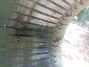
I. Failure Involving Stator Core Ablation and Slot Insulation Damage
一.Visual Observations
Localized blackening and ablation of stator laminations; heat‑induced damage to slot insulation strips with visible high‑temperature scorch marks on the surface; winding lashings at the end turns remain intact. This rules out aging caused by long‑term dust accumulation, indicating instead a sudden, short‑term overheating injury. Such failure cases are occasionally reported for motor electric 55 kw units supplied by an industrial 3 phase motor manufacturer, even for well‑designed high efficiency three phase asynchronous motor models.
二.Core Causes of Short-Term Damage After Installation
1. Installation Misalignment Leading to Rotor-Stator Rubbing (Most Common Cause)
Improper bearing assembly, significant leveling errors, or severe coupling misalignment during factory or on-site installation causes the rotor to run eccentrically and rub against the stator core. Mechanical friction generates instantaneous high heat, scorching the core surface and melting slot insulation, creating the burn marks shown in the image within a short period. As this is a new machine without accumulated long-term wear, this factor is the primary cause. Even a premium high efficiency three phase asynchronous motor, such as the widely‑used motor electric 55 kw model from a reputable industrial 3 phase motor manufacturer, can suffer this damage if installation quality is poorly controlled.
2. Wiring Errors Causing Inter-turn or Inter-phase Winding Short Circuits
Incorrect phase wiring or loose/poor terminal connections cause continuous heat generation due to contact resistance; heat spreads along the slot, scorching the core insulation. Alternatively, damaged cable insulation or moisture ingress leads to localized leakage and short circuits; rapid temperature spikes burn out slot insulation and scorch the core.This risk applies equally to motor electric 55 kw and other ratings of high efficiency three phase asynchronous motor.
3. Latent Defects from Manufacturing
Issues such as misaligned slot insulation, localized damage to enameled wire coatings, or incomplete inter-lamination insulation coating lead to localized eddy-current overheating during no-load test runs. Oversights during factory withstand-voltage testing allow these latent defects to escalate rapidly once the motor is under load on-site, resulting in visible ablation within a week.
4. Mismatched Operating Conditions + Overload/Surge
Incorrect motor selection (rated power lower than equipment load requirements) results in continuous overload upon startup. Alternatively, equipment jamming or mechanical stalling causes a massive, short term current surge; the resulting intense heat in the windings conducts to the core, causing localized burn damage. Improper application will overwhelm the design margin of even a well built high efficiency three phase asynchronous motor like the motor electric 55 kw supplied by an industrial 3 phase motor manufacturer.
5. Cooling conditions compromised on-site
During installation, motor vents were blocked by debris or the fan was installed backward, obstructing heat dissipation channels. Consequently, heat could not escape under load, leading to rapid localized heat buildup that scorched the core insulation.
II.Cracking at the reinforcing ribs of the cast-iron motor housing
Visual characteristics
Cracks are concentrated at the stress-concentration points (corners) of the reinforcing ribs. As the unit is new and free from long-term fatigue aging, the failure is attributed to short-term stress exceeding limits. This type of mechanical failure may also occur on a new motor electric 55 kw high efficiency three phase asynchronous motor.
Root causes of cracking shortly after installation
1.Highly uneven installation stress (most common)
Uneven mounting surfaces, incorrect or missing shims, excessive variance in bolt tightening torque, or localized gaps beneath the base; during operation, vibration subjects the rib corners to continuous alternating bending stress. Due to the brittleness of cast iron, cracks initiate and propagate within days. Additionally, hidden internal damage from impacts during lifting or placement can cause latent cracks to rapidly expand into visible, long cracks under operational vibration. Regardless of robust casting standards adopted by a squirrel cage induction asynchronous motor manufacturer, the ac induction motor remains vulnerable to installation induced mechanical stress.
2. Inherent casting defects
Hidden flaws—such as sand holes, shrinkage porosity, or micro-cracks—existed within the housing from the casting stage but went undetected during factory quality checks. Under on-site load vibration and thermal cycling, the structure failed rapidly at weak points along stress-concentration corners; the unit’s operation for just one week was sufficient to trigger the propagation of these defects.
3. Coaxiality misalignment amplifying vibration impact
Excessive coupling misalignment caused severe periodic vibration during operation, with the unit’s amplitude far exceeding design limits. This subjected the housing’s stress-concentration corners to continuous impact, leading to rapid fatigue cracking. Simultaneously, the vibration exacerbated stator-rotor rubbing issues, resulting in a combination of these two failure modes. Even well balanced high efficiency three phase asynchronous motor equipment such as 55 kw from a squirrel cage induction asynchronous motor manufacturer cannot resist destructive vibration caused by poor on site alignment.
4. External impact damage on-site
Hard objects struck the housing corners during installation or transport, causing surface-level micro-cracks that were difficult to detect with the naked eye; operational vibration subsequently caused these cracks to extend and lengthen. III. Interrelationship Between Fault Types & Rapid Troubleshooting Steps
III. Fault Interdependency Logic
Installation misalignment and uneven mounting feet → Excessive machine vibration: On one hand, rotor eccentricity causes the rotor to rub against the stator bore (stator bore rubbing), damaging the stator core; on the other hand, impact forces stress the casing, leading to cracking. A single installation error triggers both issues simultaneously, a pattern that aligns perfectly with the phenomenon of new units failing within the first week of operation. This combined fault scenario has been observed on field deployed motor electric 55 kw high efficiency three phase asynchronous motor products.
Priority Troubleshooting Sequence
1.Verify installation parameters: Re-check mounting foot levelness, bolt tightening torque, and coupling coaxiality; inspect ventilation openings for obstructions;these steps apply for commissioning any high efficiency three phase asynchronous motor.
2.Electrical testing: Measure three-phase winding insulation resistance and DC resistance; check for incorrect phase connections, loose contacts, or inter-turn short circuits;
3.Casting verification: Examine the fracture surface to determine if the crack stems from an original casting defect (e.g., a sand hole) or stress-induced cracking occurring later;
4.Mechanical inspection: Disassemble to check bearing assembly clearances and the uniformity of the rotor-stator air gap; confirm the presence or absence of rub marks from rotor-stator contact.